


This Arduino-based dual-mode scientific calculator is a versatile and efficient tool for both basic and advanced calculations.
In normal mode, it functions as a standard calculator, performing addition, subtraction, multiplication, and division via a 4×4 keypad.
Results appear clearly on an OLED screen. A push-button switch enables seamless toggling between modes for added flexibility.

In scientific mode, the calculator expands its functionality to handle advanced operations such as sine, cosine, tangent, and square root calculations—ideal for students, engineers, and professionals requiring trigonometric or algebraic computations.
The OLED display ensures sharp visibility, while the keypad’s multi-functional layout supports both standard and scientific inputs within a compact design.

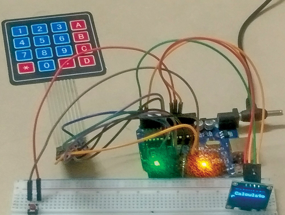
The push-button mode switch improves usability, making the setup adaptable across varied use cases. The author’s prototype is shown in Fig. 1, and the components required are listed in Bill of Materials table.
| Bill of Materials | |
| Item | Quantity |
| Arduino Uno | 1 |
| 4×4 keypad | 1 |
| OLED display (SSD1306) | 1 |
| Push-to-on switch (SW1) | 1 |
| Jumper wires | As per requirement |
Dual-Mode Scientific Calculator Circuit and Working
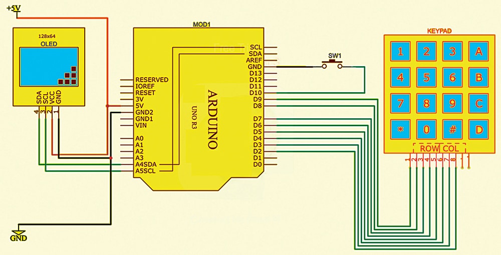
Fig. 2 shows the circuit diagram of the Arduino-based dual-mode scientific calculator. The design showcases efficient utilisation of hardware resources by combining an Arduino Uno, OLED display, and a simple keypad interface, making the device cost-effective and straightforward to implement. The internal pull-up resistor used for the mode-switching button ensures stable operation by preventing false triggers.
This calculator also provides a valuable learning opportunity for electronics and programming enthusiasts. It covers essential concepts such as keypad interfacing, display handling, and implementing mathematical computations with Arduino. Overall, this customisable and expandable design offers a practical, hands-on introduction to embedded systems development.
The hardware setup includes connecting the OLED display via the I2C protocol (VCC to 5V, GND to GND, SDA to A4, and SCL to A5). The 4×4 keypad connects to the Arduino’s digital pins, with rows attached to pins D9, D8, D7, and D6, and columns to pins D5, D4, D3, and D2. A push button is wired to ground and connected to pin D10 of the Arduino. When the button (SW1) is pressed, the calculator switches to scientific mode, displaying ‘scientific mode’ on the OLED screen.
The Arduino code is structured to detect keypad input, process numbers and operators, and update the OLED display accordingly. The loop() function continuously checks the state of the push button, toggling between standard and scientific modes. When a key is pressed, the program determines the appropriate operation based on the active mode and dynamically displays the result on the OLED.
Operating Mode of the Calculator
The calculator features three modes of operation: normal, scientific, and switching. Each is described below.
Normal: Used for basic arithmetic operations. In this mode, the keypad functions as follows:
- A – Multiplication (*)
- B – Addition (+)
- C – Subtraction (-)
- D – Division (/)
- * – Clear input
- # – Execute calculation
Scientific mode: Enables advanced operations. In this mode, the same keys are reassigned to:
- A – sin (value)
- B – cos (value)
- C – tan (value)
- D – sqrt (value)
- * – Clear input
Switching: The push button connected to pin D10 of the Arduino toggles between normal and scientific modes.
Arduino Code for Dual-Mode Scientific Calculator
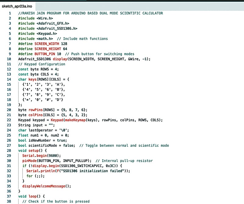
The source code for the calculator has been developed using the Arduino IDE. The Adafruit SSD1306 OLED display library and the Keypad.h library are required. Once the libraries are added, the code can be uploaded to the Arduino by selecting the appropriate port and board. Fig. 3 shows a snippet of the source code.
Construction and Testing
After uploading the source code to the Arduino Uno, the components should be assembled as shown in the circuit diagram (refer Fig. 2). A 12V, 2A adaptor must be connected to the Arduino Uno’s DC power socket.
To operate the calculator, first check the current mode. If switching modes is required, press the push button (SW1). The selected mode will then be active and ready for use.
Rakesh Jain, Assistant Professor in ECE Department in Geetanjali Institute of Technical Studies, Udaipur, holds a master’s degree in VLSI, BE degree in electronics and communication, and diploma in electronics. His research areas are sensors and microcontrollers, and he has 31 copyrights, 9 design patent registrations, 3 Indian utility patents, and 17 projects in EFY to his credit. He is recipient of Mewar Scientist Award 2023.