


The design uses energy from a current transformer to power a fault indicator, stores energy in a supercapacitor, and includes a backup battery.
The TIDA-01385, reference design from Texas Instruments (TI) features a circuit that captures energy from a current transformer to power the fault indicator’s system load, while storing surplus energy in a 2.7 V supercapacitor. A primary Li/SOCl2 battery serves as a backup power source, extending the fault indicator’s operation when the power grid fails. Capable of handling input currents ranging from 3 mA to 2 A, this Design delivers a stable 3.6 V output to the system load within 2 seconds of connecting the current transformer. The design is specifically suited for fault indicator applications.
A fault indicator is a device used in electric power distribution networks to detect and signal fault conditions. By pinpointing the exact section of the network experiencing a fault, these indicators help reduce operational costs and minimize service interruptions. To rapidly identify the type and location of faults, modern fault indicators are designed to record operational data from the power network and transmit this information to a data concentrator via low-power wireless communication when necessary.

The power for the fault indicator is supplied primarily through energy harvesting devices, with a primary battery serving as a backup. Typical energy harvesting sources include current transformers (CTs) or solar cells. Since the energy output from a CT depends on the current flowing through power lines, and solar cell output varies with sunlight conditions, an energy buffer such as a supercapacitor or rechargeable battery is necessary to ensure a stable power supply. The reference design presents a circuit that harvests energy from a CT to charge a supercapacitor, providing a stable power source for the system load.
The design takes power from the secondary side of a current transformer (CT), with a maximum input current of 2 A and a typical minimum current above 3 mA, depending on the system load. The AC input from the CT is converted to DC using a full-bridge rectifier. When the supercapacitor is fully charged, an overcharge protection circuit diverts excess current to ground. Once the voltage drops below a certain level, charging resumes. The charging circuit only allows the supercapacitor to charge when the input voltage is above 1.6 V, ensuring enough power for the system even if the supercapacitor starts at zero voltage.

A monitor circuit helps manage the supercapacitor’s charge level to prevent overcharging. A boost converter increases the voltage to a steady 3.6 V to power the system load, which also helps avoid draining the battery during normal conditions. The backup battery is connected through a Schottky diode and provides power when the grid fails and the supercapacitor is empty. This setup ensures a stable and reliable power supply for the fault indicator system.
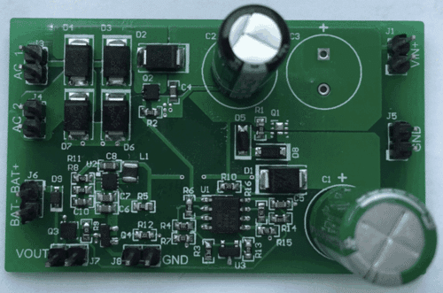
TI has tested this reference design. It comes with a bill of materials (BOM), schematics, assembly drawing, printed circuit board (PCB) layout, and more. The company’s website has additional data about the reference design. To read more about this reference design, click here.